Blogs
Don't forget to read some blogs!

WE ARE NOT A FAMILY IN THE COMPANY!
Of course, we are a team at work; We are not family.
We have a vision and a mission or a purpose and we can communicate on these grea...

B2B MARKETING AND SALES DICTIONARY
A To Z B2B marketing and sales terms that may help to your sales process.
More
BIDUSTRY: A PLATFORM TO REACH INDUSTRIAL MANUFACTURERS AND SUPPLIERS!
Procurement teams in companies have been searching for industrial products online for many years.
The Internet is very important for sou...
More
ARE YOU AN INDUSTRUAL MANUFACTURER OR SUPPLIER? HERE'S HOW TO GET STARTED AT BIDUSTRY:
Bidustry is a B2B marketplace for industrial sellers and buyers. Industrial manufacturers and suppliers serving products at Bidustry.
It...
More
COMPARISON OF YOUR COMPANY WEBSITE AND BIDUSTRY AS AN INDUSTRIAL B2B MARKETPLACE
Serving products on your own website?
The point is that is inbound marketing. SEO is one of the inbound marketing strategies.
In...
More
BIDUSTRY IS CHANGING THE WAY B2B MARKETPLACE WORKS
Companies have been searching for platforms to reach potential customers besides their websites in the last 5 years. The Pandemic also sped up t...
More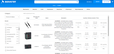
WHY DO MANUFACTURERS AND SUPPLIERS NEED THE INDUSTRIAL B2B MARKETPLACE: BIDUSTRY!
Inbound marketing is so important for B2B working companies. The key point is the distribution of contents and resources.
More
BUILDING BRIDGES TO YOUR COMPANY WITH B2B MARKETPLACES AND OTHER METHODS
Today most companies have been struggling to reach leads. On the other hand, the internet is a good way to reach leads.
There are differ...
More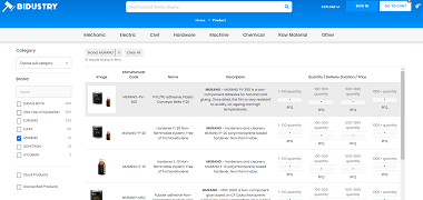
A GUIDE TO SET UP & OPTIMIZE A BUYER PROFILE ON INDUSTRIAL B2B MARKETPLACE: BIDUSTRY!
Bidustry is B2B marketplace for industrial sellers and buyers!
Buyers are mostly factories, plants, refineries, industrial facilities, b...
More
LOOKING TO BUY CHEMICAL GOODS? RFQ NOW ON BIDUSTRY! TOP 20 OF DECEMBER 2022
Looking to buy chemical goods! RFQ now on Bidustry! What are top 20 chemical goods of December 2022?
Before starting you should be aware...
More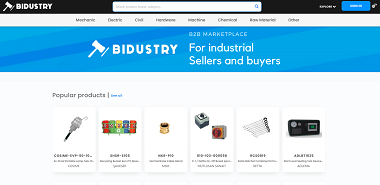
A GUIDE TO SET UP & OPTIMIZE A SELLER PROFILE ON INDUSTRIAL B2B MARKETPLACE: BIDUSTRY!
Bidustry is B2B marketplace for industrial sellers and buyers. There are two types of goods:Industrial and consumer...
More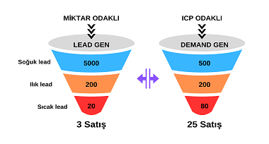
WHAT ARE DEMAND GENERATION METRICS?
The purpose of Demand Generation is to increase potential customer awareness through brand awareness.
Let's consider the awareness level...
More
DIFFERENCES BETWEEN LEAD GENERATION AND DEMAND GENERATION
Differences between Lead generation and Demand generation:
1- LEAD GENERATION focused on quantity. DEMAND GENERATION focused on targeted...
More
CREATE A LONG-TERM PLAN FOR YOUR COMPANY!
You want to create a long-term road map for your company. You want to set up a system. Do you want to be sustainable?
A damage assess...

SUSTAINABLITY COMES FROM MARKETING MINDSET!
You cannot be sustainable without a marketing mindset in your company. Marketing is mindset not only operation.
Your system is consta...

MANUFACTURING OR MARKETING SELLS?
It is an accepted misconception that production, in particular, will increase sales on its own rather than marketing.
In fact, manufa...

IT IS NOT DIGITAL MARKETING VS TRADITIONAL MARKETING!
Digital marketing VS. traditional marketing is not right!
For example:
Pops (pop up/under) are digital but outbound market...

HOW DO YOU SET YOUR SALES GOALS?
So how do you set your sales goals?
Of course, you check your company memory! CRM. Do you?
It's better if you use CRM, but...

ARE YOUR WEBSITE COPY GOOD ENOUGH?
You've purchased or created a website template and are trying to fill in the blanks.
Copywriting in marketing is not like that. It's ...

YOU CAN'T BE EVERYTHING TO EVERYONE!
You can't be everything to everyone!
We can supply everything. We can produce anything! We solve everything for you. We are the solut...

CONTENT DISTRIBUTION ON SOCIAL MEDIA-1
In B2B, creating and distributing content on social media is an issue.
There are many blogs, posts, recommendations, recipes, etc. re...

SALES FUNNEL VS FLYWHEEL SHORT DEFINITION
It is a fact that the basis of all healthy growth companies we see today, as a case study, is word of mouth marketing (WoM), triggered by happy ...
More
WHAT IS BUYER ENABLEMENT?
"Buyer enablement"
Most people around the global still struggling about what are lead, prospect, Opportunity? While focusing on these...
Differences between lead generation and demand generation-1
Demand generation VS lead generation may seem a bit confusing.
More
6 TIPS TO INCREASE YOUR LEADS FROM INBOUND SOURCES & HOW TO USE BIDUSTRY IN THIS WAY!
B2B working companies have annual sales goals. In the last ten years some of those companies started to have sales goals upon internet. They mos...
More
1-BENEFITS OF USING A B2B MARKETPLACE FOR MANUFACTURERS AND SUPPLIERS!
Today manufacturers and suppliers have been searching platforms to start healthy marketing and sales activities.
More

A COMPARISON OF TRADITIONAL SOURCING METHODS VERSUS USING A B2B MARKETPLACE!
For many years, people in companies have been trying to reduce costs of time and money. When you think about companies, their purchasing is not ...
More
DIFFERENCES BETWEEN MARKETING, SALES AND BUSINESS DEVELOPMENT
Today, businesses offer their products and services to potential customers through models such as B2B, B2C, C2C. Businesses create strategies at...
More
B2B LEAD GENERATION IN PANDEMIC WORLD
With the pandemic, companies have turned to technology tools in finding potential customers. E-commerce showed a different increase in 2020 comp...
More
WHAT ARE DIFFERENCES BETWEEN B2B, B2C AND C2C MARKETPLACES?
With the development of technology, sellers turned to marketplaces in order to reach buyers using search engines. Marketplaces have gained...
More
MANUFACTURING AND PURCHASING IN INDUSTRIAL FACILITIES
Industrial product, consumption product, etc. products are delivered to the customer as a result of different production types according t...
More
DEVELOPMENT OF PROCUREMENT AND NEW TRENDS
The purchasing process differs in various product categories. When examining according to product categories, 2 concepts come to the fore...
More
WHAT IS PROCUREMENT? WHAT ARE MAIN PROBLEMS?
Procurement is simply the acquisition of materials and services from product sellers or service providers on a specified schedule. As an individ...
More
B2B MARKETPLACE IN DIGITALIZATION
What is the marketplace?
Marketplace is a platform that allows businesses or consumers to trade globally or loca...
More
DIFFERENCES BETWEEN COLD CALL AND TELEMARKETING
There are differences between Cold Calling and Telemarketing. What are they?
1- The purpose of Cold Calling is to continue the conver...
DIFFERENCES BETWEEN INDUSTRIAL GOODS AND CONSUMER GOODS
Consumer products are goods that are used to meet daily needs and are mostly preferred on an individual basis. Usually they are low purchasing a...
More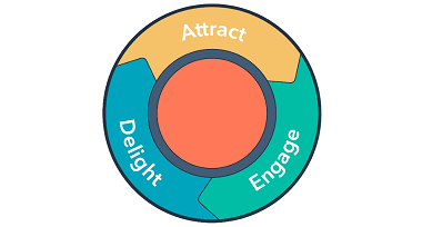
WHAT IS INBOUND MARKETING? HOW CAN BIDUSTRY HELP?
Inbound marketing is about creating marketing and sales that people love by providing helpful content and resources that attract people to you a...
More
LOOKING TO BUY MECHANICAL PARTS! WHAT ARE TOP 20 DECEMBER 2022?
Looking to buy mechanical parts! RFQ now on Bidustry! What are top 20 mechanical goods of December 2023?
More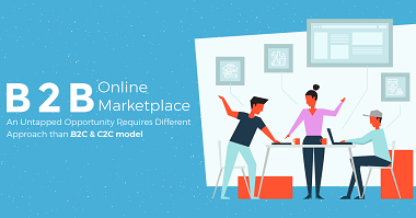
THE POTENTIAL OF CROSS-BORDER TRADE AND ADVANTAGES WITH A B2B MARKETPLACE
For many years, people in companies have been exploring about trading cross-border and increasing brand awareness globally.
When you thi...
More
INBOUND MARKETING vs. OUTBOUND MARKETING FOR COMPANIES!
For many years, marketing has been changing it’s form and coming us within different ways. The internet has also become a key actor in the...
More
LOOKING TO BUY ELECTRICAL PARTS? RFQ NOW ON BIDUSTRY!: TOP 20 ELECTRICAL GOODS OF DECEMBER 2022
Looking to buy electrical parts? RFQ now on Bidustry!: Top 20 electrical goods of the last month, you can find on Bidustry.
Sellers are ...
More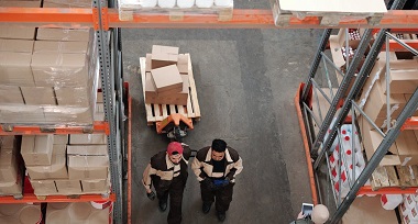
B2B MARKETPLACE FOR INDUSTRIAL SELLERS AND BUYERS?
B2B marketplace for industrial sellers and buyers? Whaaat?!
There are 10 million factories around the world. In addition to this, constr...
More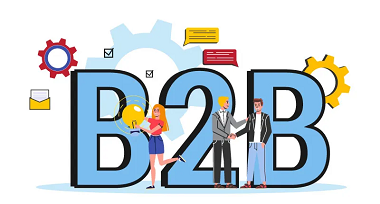
B2B E-COMMERCE MAY NOT BE WHAT YOU THINK!
If you are an industrial goods manufacturer or a supplier, e-commerce may not satisfy your expectations.
E-commerce (electronic commerce...
More
DO YOU HAVE UNLIMITED PAID ADS BUDGET FOR YOUR COMPANY?
Do you have unlimited paid ads budget for your company?
Maybe you are performance marketing addicted?
The truth is most companie...
More
WHAT ARE 3 BENEFITS OF MARKETPLACES? WHICH ONE IS FIT FOR YOU?
What are 3 benefits of marketplaces? How can we decide which one is fit for us?
Most marketplaces offer 3:
-To Increase br...
More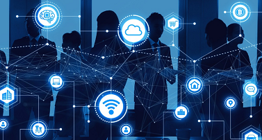
DIGITALIZATION AND PURCHASING DURATION
Today, businesses adopt themselves to the digitalization by investing in social media, cloud technologies and big data so as to build a connecti...
More
PROJECT PLANNING AND MANHOUR, COST CALCULATION IN INDUSTRIAL FACILITIES
Industry sector has been following major contract projects which are succesfully signed by construction companies in recent years. Those c...
More
ELECTRICAL AND INSTRUMENTATION INSTALLATION PERIOD IN INDUSTRIAL FACILITIES
An industrial facility means a facility engaged in activities such as an agriculture, a forestry, a fishing, a mining, a production, a transport...
More
SMALL DICTIONARY THAT CONTAINS INDUSTRIAL TERMS
You may check mini industrial terms dictionary. It includes industrial terms.
More
DIFFERENCES BETWEEN PROCUREMENT AND PURCHASING
Companies have developed various methodologies so as to provide themselves optimum material and service from the past to present. These methodol...
More
6 TECHNOLOGICAL INNOVATIONS FOR INDIRECT PURCHASING
Since 2011, indirect expenses have increased by 7% per year, according to Mckinsey & Company. Despite this rate, companies find it difficult...
More
PURCHASING AND BIDUSTRY IN PANDEMIC WORLD
The corona virus has affected industrial electrical, mechanical and civil product suppliers such as exporters, distributors, and retai...
More
CATEGORY MANAGEMENT WITH BIDUSTRY IN INDUSTRIAL PRODUCTS
Bidustry is a B2B marketplace for industrial product sellers and buyers.
There are 2 types of products:
Manufacturer goods...